
Last Updated: 2026-11-10
- Calibration = compare first, adjust only if needed. Test 5 points (0/25/50/75/100%) up and down, record as-found, and adjust only points outside tolerance.
- Error in % of span = (measured mA − expected mA) ÷ 16 × 100. On a ±0.5% FS transmitter the allowed band is only ±0.08 mA, so your mA meter matters as much as your pressure reference.
- Use at least a 4:1 reference. Checking a ±0.5% FS transmitter needs a reference of about ±0.125% FS or better on a similar range, before adding the mA meter to the uncertainty budget.
- Re-ranging a HART transmitter is not calibration. Only sensor trim and output trim against a reference correct measurement error.
- The SIBXSUN YLEX01 datasheet specifies eight-point standard calibration and four-point detection across full scale, and smart models such as the YL6200 list ≤0.1% FS/year long-term stability.
Quick Answer: How Do You Calibrate a Pressure Transmitter?
Isolate the transmitter, apply known pressures from a reference at 0, 25, 50, 75 and 100% of range (rising, then falling), read the output, and compare each reading with the ideal value. If every point is inside the tolerance, the transmitter passes and you record the as-found data without touching it. If not, adjust zero first, then span (analog units) or run a sensor trim (HART units), and repeat the full test to record as-left data.
That is the whole method. The rest of this guide covers the details that decide whether the result is trustworthy: the reference accuracy, the mA arithmetic, what “zero”, “span” and “trim” really change, a short note on wiring, and the field checks that catch most problems before anyone opens a calibrator case.
The procedure here follows the general test methods in IEC 61298-2 (performance evaluation of process measurement devices) and is written for typical industrial piezoresistive and monocrystalline silicon transmitters. Always check the manual of the specific transmitter first.
What Calibration Means (and What It Does Not)
Calibration is a comparison between the transmitter and a reference standard with known, smaller uncertainty. Adjustment is a separate, optional step. Two practices follow from this:
- Record as-found before you touch anything. The as-found result tells you whether the loop was measuring correctly since the last check. If you adjust first, that information is lost.
- Do not “improve” a transmitter that is already inside tolerance. Each adjustment adds the uncertainty of the reference and the technician. Repeated trims on a good unit can make it worse, not better.
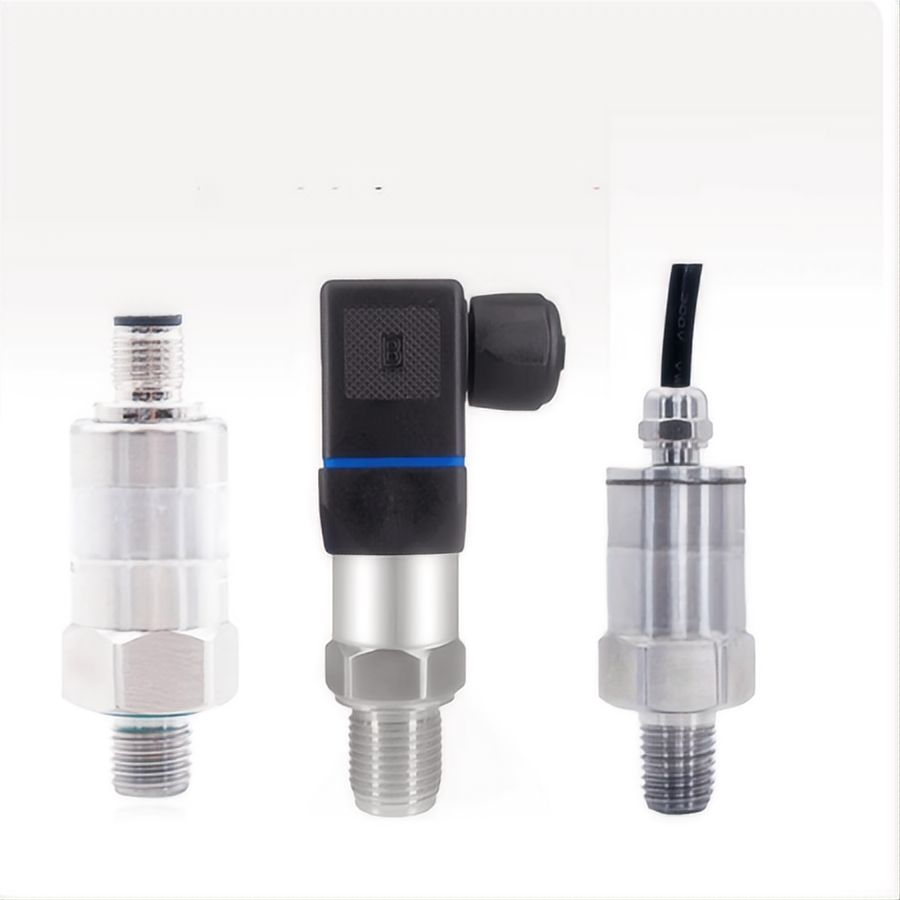
Transmitters sold as “pre-calibrated” are a good example. The SIBXSUN YL805 industrial pressure transmitter datasheet describes the unit as pre-calibrated with no need for field calibration. For a sensor like that, the field job is a verification check at a few points, not an adjustment.
What Equipment Do You Need?
| Item | Purpose | What to check |
|---|---|---|
| Pressure source (hand pump, comparator or controller) | Generates stable test pressures | Covers the full range; fine adjustment (vernier) for small steps |
| Reference gauge or pressure module | The standard you compare against | Valid calibration certificate, ideally from an ISO/IEC 17025 lab; at least 4:1 better than the tolerance |
| mA meter (or documenting calibrator) | Reads the 4-20mA output | 0.01 mA resolution or better; its own uncertainty counted in the budget |
| Loop power supply, 24 V DC | Powers 2-wire transmitters on the bench | Within the transmitter supply range (for example 12–30 V DC on YL4200 current versions) |
| 250 Ω resistor | Needed for HART communication | HART needs at least 230 Ω in the loop |
| HART communicator or modem | Sensor trim, output trim, re-range | Only for smart transmitters |
| Vacuum pump or barometric reference | Zero for absolute-pressure transmitters | Venting to atmosphere is not zero for absolute units |
The 4:1 rule in numbers
| Transmitter accuracy | Tolerance at 20 mA span | Reference needed (4:1) | Is a ±0.25% FS digital gauge enough? |
|---|---|---|---|
| ±1% FS | ±0.16 mA | ±0.25% FS | Yes, at the same range |
| ±0.5% FS | ±0.08 mA | ±0.125% FS | No, only about 2:1 |
| ±0.25% FS | ±0.04 mA | ±0.0625% FS | No |
| ±0.1% FS | ±0.016 mA | ±0.025% FS | No, use a lab-grade module |
| ±0.075% FS | ±0.012 mA | ±0.019% FS | No, use a lab-grade module |
The reference must also be compared over a similar range. A ±0.05% FS module rated for 0–700 bar is far worse than ±0.05% of reading when you use it to check a 0–1 bar transmitter. As a practical example, the YLB80 digital pressure gauge is rated ±0.25% or ±0.4% FS: useful for quick field checks on ±1% FS sensors, not as the reference for a precision smart transmitter.
How to Calibrate a Pressure Transmitter: Step by Step
1. Prepare and isolate
Get the loop put in manual or bypass with operations, isolate the process valve, and vent the transmitter safely. For differential pressure transmitters, close the block valves and open the equalising valve on the 3-valve or 5-valve manifold to check zero; then close the equalising valve, apply test pressure to the high side and vent the low side to atmosphere for the up/down test. Let the transmitter and the reference reach the same temperature; a unit taken straight from a hot pipe rack to a cold workshop will drift during the test.
2. Connect pressure and electrical sides
Connect the pressure source and reference to the process port with clean, leak-free fittings. On the electrical side, a 2-wire 4-20mA transmitter needs only the loop supply and the mA meter in series. Leak-test at the top pressure for a minute before you start: a falling reading at a fixed pump setting is a leak, not a calibration error.
3. Run the as-found test, rising then falling
Apply 0, 25, 50, 75 and 100% of the calibrated range, then come back down through 75, 50, 25 and 0%. Approach each point from one direction without overshooting, wait for the reading to settle, and record both the reference pressure and the output.
Worked example for a 0–10 bar transmitter, ±0.5% FS:
| Test point | Pressure | Expected output | Allowed band (±0.08 mA) | Example as-found | Error (% span) |
|---|---|---|---|---|---|
| 0% | 0.0 bar | 4.000 mA | 3.920–4.080 | 4.050 mA | +0.31% ✓ |
| 25% | 2.5 bar | 8.000 mA | 7.920–8.080 | 8.060 mA | +0.38% ✓ |
| 50% | 5.0 bar | 12.000 mA | 11.920–12.080 | 12.070 mA | +0.44% ✓ |
| 75% | 7.5 bar | 16.000 mA | 15.920–16.080 | 16.090 mA | +0.56% ✗ |
| 100% | 10.0 bar | 20.000 mA | 19.920–20.080 | 20.100 mA | +0.63% ✗ |
For a linear-output transmitter, the expected current at any pressure is I = 4 + 16 × (P − Pmin) ÷ (Pmax − Pmin), and the error is (Imeasured − Iexpected) ÷ 16 × 100. A DP transmitter configured for square-root (flow) output follows a different curve: 25% of differential pressure gives 12 mA, not 8 mA, so check the transfer function before you judge a point as failed. The full conversion between mA and pressure, including compound ranges, is explained in our 4-20mA vs RS485 Modbus vs HART output signal guide.
The pattern in the example (small error at zero, growing towards full scale) points to a span error, not a zero error. Reading the shape of the errors before adjusting saves time:
- Same offset at every point → zero shift.
- Error grows with pressure → span error.
- Rising and falling readings differ at the same point → hysteresis, often mechanical stress, a damaged diaphragm or a sticky manifold valve.
- Middle points off while ends are fine → non-linearity, which a two-point zero/span adjustment cannot fix.
4. Adjust only if outside tolerance
On an analog transmitter, set zero at 0% first, then span at 100%, then recheck zero, because the two often interact. Repeat until both ends are inside a fraction of the tolerance. On a HART transmitter, use the procedures in the next section.
5. Run the as-left test and document
Repeat the full 5-point rising and falling test. Record the transmitter tag and serial number, reference ID and certificate due date, ambient temperature, as-found and as-left data, and the pass/fail decision. Those records are what let you set a sensible calibration interval later.
Zero, Span, Re-Range and Trim: What Each One Changes
Most calibration mistakes on smart transmitters come from mixing these up.
| Operation | Applies to | What it changes | Needs a pressure reference? | Corrects sensor error? |
|---|---|---|---|---|
| Zero adjust | Analog | Output at lower range value (4 mA) | Yes (or vented/equalised) | Offset only |
| Span adjust | Analog | Output at upper range value (20 mA) | Yes | Gain only |
| Re-range (LRV/URV) | Smart / HART | Which pressures map to 4 and 20 mA | No (when keyed in) | No |
| Sensor trim (lower/upper) | Smart / HART | The digital pressure reading itself | Yes | Yes |
| Output (D/A) trim | Smart / HART | The mA value driven onto the loop | No pressure; needs accurate mA meter | No, corrects the output stage |
| Zero trim (installed) | Smart / HART | Offset caused by mounting position or static pressure | Vented or equalised | Offset only |
Two practical rules:
- Re-ranging with a communicator is configuration, not calibration. It changes the scale, but if the sensor reads 2% high, it still reads 2% high after re-ranging.
- Trim in the right order: output (D/A) trim first so the mA loop is right, then sensor trim, then a full as-left test. Avoid routine sensor trims on transmitters that are already in tolerance, including new units.
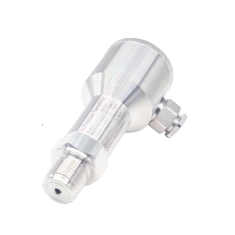
Smart models such as the YL2088 smart monocrystalline silicon pressure transmitter and the YL6200 smart pressure transmitter use digital compensation, so their adjustments go through the communicator or local keys rather than potentiometers. The YL6200 datasheet lists a 250–600 Ω load range for HART communication.

Wiring Before You Calibrate: 2-Wire, 3-Wire and 4-Wire
Many “calibration failures” are wiring problems. In short: a 2-wire transmitter is loop-powered, with supply and 4-20mA signal on the same pair; a 3-wire transmitter adds a separate signal wire to a shared common, typical for 0-5V or 0-10V outputs; a 4-wire transmitter has separate supply and signal pairs, as with RS485 Modbus or I2C. On the YL4200 industrial pressure transmitter, the datasheet lists current output as 2-wire at 12–30 V DC, voltage output as 3-wire (6–24 V DC for 0–5 V, 12–30 V DC for 0–10 V), and RS485 as 4-wire at 5–30 V DC. Wrong supply voltage, a missing 250 Ω resistor for HART, or a voltage-output unit wired as if it were 2-wire will all look like calibration errors. Loop voltage budgets and cable limits for each output are covered in the 4-20mA vs RS485 vs HART guide.
Field Checks: What to Do Before Pulling a Transmitter
A quick in-place check often tells you whether a full bench calibration is needed.
| Symptom | Quick check | Likely cause |
|---|---|---|
| Output 0 mA | Measure loop voltage at transmitter terminals | Open circuit, blown fuse, reversed polarity |
| Output ≤3.6 mA or ≥21 mA | Read diagnostics via HART or local display | Transmitter in failure alarm (NAMUR NE 43 levels) |
| Reading drops at high pressure only | Measure terminal voltage at 20 mA | Supply too low or loop resistance too high |
| Constant offset after installation | Vent or equalise, read output | Mounting position: do a zero trim, not a span adjustment. A wet leg or remote seal head is not a sensor error; build it into the LRV/URV instead |
| Offset on a DP transmitter under line pressure | Equalise at line pressure, compare with zero at atmosphere | Static pressure zero effect |
| Noisy or jumping reading | Check shield grounding and cable routing near VFDs | Electrical noise |
| Liquid-filled impulse line reads wrong | Account for height difference | Hydrostatic head: 1 m of water ≈ 9.81 kPa (0.098 bar) |
For an absolute transmitter, venting to atmosphere gives about 1.013 bar, not zero. Use a vacuum reference or a calibrated barometer to check zero. The differences between gauge, absolute and sealed references are explained in gauge vs absolute vs differential pressure, and head-of-liquid conversions are in our pressure units explained guide.
How Often Should You Calibrate?
There is no universal interval; regulators, insurers and your own quality system may set one for safety or custody-transfer loops. For ordinary process loops, a reasonable approach is:
- Start at 12 months for new installations.
- Compare long-term stability with your tolerance. Datasheet values in the SIBXSUN range include ±0.2% FS/year for the YL2088 and ≤0.1% FS/year for the YL6200. With a ±0.5% tolerance, a transmitter drifting 0.1% per year leaves much more margin between checks than one drifting 0.2%.
- Adjust by as-found history. If several consecutive as-found results are well inside tolerance, extend the interval; if a unit is found out of tolerance, shorten it and review the process data since the last pass.
- Recalibrate after events, not only by calendar: overpressure, lightning or welding near the loop, process upsets, or a change of range.
Overpressure deserves attention. Datasheet overload ratings in the range run from 150% FS on the YLEX01 and YL2088 to about 2× on many compact models; a hydraulic spike above that can shift zero permanently, and no field trim will make the sensor reliable again.
What Calibration Data Should Come From the Supplier?
Field calibration is easier when the transmitter arrived well characterised. When you buy, ask for:
- the calibration or test points used at production and whether rising and falling points are included;
- the as-shipped readings per serial number, or at least a batch test record;
- the reference used and its traceability;
- the configured range, output and damping, so re-ranging is not needed on site.
As one example from our range, the YLEX01 explosion-proof pressure transmitter datasheet specifies eight-point standard calibration and four-point detection covering the full scale, with laser marking for product traceability. Ask us which test record ships with the model and quantity you order.
Sourcing Notes: MOQ, Lead Time and What to Send
SIBXSUN supplies pressure transmitters from partner production lines in China with MOQ from 1 piece for most products, which suits replacement units and spare stock. In-stock configurations ship in 2–3 days; custom ranges, outputs or connections typically take 15–30 days. Range, output signal, process connection and cable length can be specified per order, so the transmitter can arrive ranged for its loop. Pricing is FOB Ningbo, with CIF available.
To quote quickly, send the pressure type and range, medium and temperature, required accuracy, output and receiving device, supply voltage, process and electrical connection, quantity and destination.
Related Guides
- How to choose a pressure transmitter: 8-step selection guide
- Types of pressure transmitters: gauge, absolute, differential, hydrostatic and smart HART
- Pressure sensor vs pressure transmitter: what’s the real difference?
- 4-20mA vs RS485 Modbus vs HART: choosing the output signal
Frequently Asked Questions
How do you calibrate a pressure transmitter?
Isolate the transmitter, connect a pressure source and reference on the pressure side and a loop supply plus mA meter on the electrical side. Apply 0, 25, 50, 75 and 100% of range rising and then falling, and convert each reading to error with (measured mA − expected mA) ÷ 16 × 100. If every point is within tolerance, record as-found and leave it alone. Otherwise adjust zero, then span (or run a HART sensor trim), and repeat the full test for as-left data.
What is the difference between zero, span and sensor trim?
Zero sets the output at the lower range value (4 mA) and span sets it at the upper range value (20 mA). On a HART transmitter, re-ranging only changes which pressures map to 4 and 20 mA; sensor trim corrects the digital pressure reading against a reference; output (D/A) trim corrects the mA the electronics drive. Re-ranging is not calibration.
How often should a pressure transmitter be calibrated?
Many plants start at 12 months and adjust based on as-found results. Compare the transmitter’s long-term stability with your tolerance: a 0.1% FS/year smart transmitter on a ±0.5% loop usually justifies a longer interval than a 0.2% FS/year unit. Safety and custody-transfer loops follow their own rules.
How accurate must the calibration reference be?
Aim for at least a 4:1 accuracy ratio, then add the mA meter and other contributions to the uncertainty budget. For a ±0.5% FS transmitter that means a reference of about ±0.125% FS or better over a similar range. A ±0.25% FS digital gauge is fine for checking ±1% FS sensors but not for calibrating a ±0.25% FS transmitter.
What is the difference between a 2-wire, 3-wire and 4-wire transmitter?
A 2-wire transmitter is loop-powered: two wires carry supply and the 4-20mA signal. A 3-wire unit has supply, common and a separate signal wire, typical for 0-5V or 0-10V outputs. A 4-wire unit has separate supply and signal pairs, as with RS485 Modbus or I2C. On the YL4200, current output is 2-wire at 12–30 V DC, voltage output is 3-wire and RS485 is 4-wire.
Ready to specify or replace a transmitter? Browse our pressure sensors and transmitters or send your range, accuracy, output and quantity and we will reply with a matched model, datasheet and FOB Ningbo quotation.